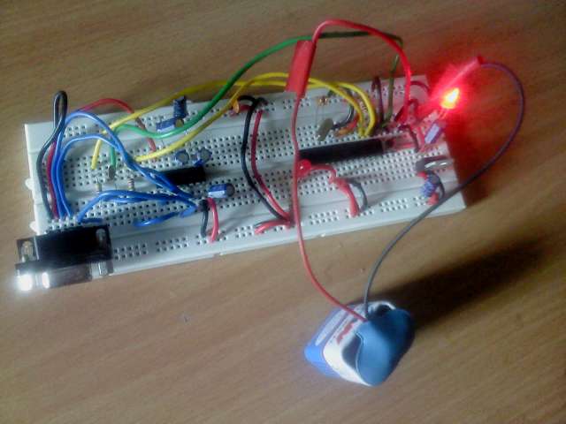
Hello!
Here’s a complete guide on making your own standalone arduino on a breadboard. By the end of this tutorial you should be be able to assemble,bootload and program your breaduino.
List of components:
- A breadboard
- Connecting wires
- Mini Push button Switch (1)
- Resistors- 220 ohm(2), 10k (1) ,1k(2)
- Capacitors- 22pF(2), 100nF(2) , 1uF(5), 10uF(2)
- 16Khz crystal (1)
- LEDs (2)
- 5V voltage regulator LM7805 (1)
- Atmega168 or Atmega8 (1) … I used an Atmega168A-Pu
- Max232 (1)
- DB9 female pin (1)
- Single row male pins
- RS232 cable (1)
- If your Atmega chip is not already bootloaded- you’ll need an AVR-ISP or you can simply use an Arduino UNO/Duemilanove as an ISP (that’s what i did)
- Computer with a serial port or a serial-to-USB converter if you don’t have one.
- A 9v dc power supply/battery
Now that we have all the components lets start building our breaduino 😀
The Schematic:
A few points to remember while breadboarding
- Keep the wires short.
- Use 2 polar capacitors for the power supply circuit.
- You can add a 100n Decoupling capacitor (smoothening cap) between VCC and GND of the Atmega chip. Make sure you put it as close to the chip as possible. This is optional but i would recommend it.
- Use 5 polar Capacitors for the MAX232 as shown. Again keep them as close to the MAX232 as possible. But if you are using a MAX3232 instead- then 100n non polarized caps would suffice. Check the data sheet of the chip that you are using.
- Leave some space ( say 5 to 6 slots) free. This will be needed to plug in the DB9 pin into your breadboard (without this you cannot interface the breaduino with a computer)
To be able to program the breaduino you need a Serial connection to your PC. Solder 4 single row male pins onto the pins 2,3,4,5 of the female DB9 connector as shown.
The end product should look like this-
Now to install the bootloader-
A microcontroller can be programmed in 2 ways. You can either do with the help of a programmer which is a separate piece of hardware OR you could have a small piece of program inside your microcontroller which would allow you to upload programs without any external hardware. This small piece of program is known as the bootloader.
I used westf’s optiloader to Burn the bootloader onto my blank Atmega chip.
The following links should help-
https://github.com/WestfW/OptiLoader
http://www.3guys1laser.com/blog-burn-bootloader-blank-atmega328atmega328p-arduino-uno
Note that optiloader will by itself load the correct bootloader depending upon the type of chip i.e Atmega168,Atmega328 or Atmega8
To check if optiloader has successfully burned the bootloader- Power up your breaduino and press the reset button. If the LED at pin 19 blinks 3 times then you have bootloaded the chip successfully
Note that for the Atmega168 with optiboot (as installed by optiloader), you will need to modify the boards.txt file in the arduino folder and add “ATmega168 with optiboot” board type. The default 168 board type assumes a different bootloader that runs at a different bit rate.
copy the following in boards.txt-
uno168.name=ATmega168 with optiboot
uno168.upload.protocol=arduino
uno168.upload.maximum_size=15872
uno168.upload.speed=115200
uno168.bootloader.low_fuses=0xff
uno168.bootloader.high_fuses=0xde
uno168.bootloader.extended_fuses=0x05
uno168.bootloader.path=optiboot
uno168.bootloader.file=optiboot_atmega168.hex
uno168.bootloader.unlock_bits=0x3F
uno168.bootloader.lock_bits=0x0F
uno168.build.mcu=atmega168
uno168.build.f_cpu=16000000L
uno168.build.core=arduino
uno168.build.variant=standard
You are now ready to program your breaduino!!
Connect the breaduino to the serial port of your comp, launch the arduino IDE, select the serial port in the “serial port” option (COM1,ttys0) , select the board type in the “board” option. In our case the “Atmega168 with optiboot”
You are now ready to upload sketches. Verify by uploading the blink sketch.
B-)

